Plate Heat Exchangers for AI Data Center CDUs: A Selection Primer
Aiprel
professor
An AI rack crossed 100 kW somewhere around 2024 and has not looked back. The GB300 NVL72 draws up to about 142 kW per rack; the Vera Rubin NVL72, in full production since mid-2026, is estimated at 190–230 kW with a warm-water loop designed around 45°C supply; the racks after that are discussed in the hundreds of kilowatts. Air stopped being an option near 50 kW per rack, as Uptime Institute’s survey data has tracked for years. Direct-to-chip liquid cooling now carries the majority of new AI capacity, and every direct-to-chip loop passes through one component that both the IT side and the facilities side depend on: the data center CDU heat exchanger inside the coolant distribution unit.
That component is a plate heat exchanger in the overwhelming majority of designs. It is also where the two worlds meet — the treated technology loop on one side, the facility water system on the other — and where most of the decisions that determine rack inlet temperature, pump energy, floor space and ten-year maintainability are quietly made. This primer walks through what the CDU duty actually demands, which plate constructions fit it, and where each one stops.
The quick answer
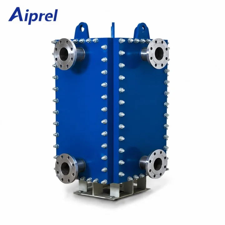
Gasketed plate-and-frame is the default for liquid-to-liquid CDU duty: the tightest approach per unit volume, openable for inspection, extendable in plate count, and cleanable by hand. Specify 316L plates, EPDM or FKM gaskets matched to the coolant, and no copper in the technology cooling loop.
Semi-welded fits asymmetric loops — for example a high-rise chilled-water riser on one side at elevated pressure, with the technology loop kept on gasketed, openable channels.
Fully welded plate-and-frame and plate-and-shell remove the elastomer entirely: for high-pressure risers, elevated temperatures, or where the design team wants no gasket in the technology path at all. Plate-and-shell also covers large facility-level duties where a pressure-vessel envelope is preferred.
Brazed plate is usually the wrong answer in a CDU, despite its compactness: standard copper brazing is galvanically incompatible with the aluminium cold plates upstream, and the pack cannot be opened. There are niche exceptions — small sealed skids with all-stainless loops — but they are the exception, not the default.
One number frames everything that follows: the approach temperature. Commercial liquid-to-liquid CDUs are typically rated at 4–5°C approach; a well-specified plate pack can do 1–2°C in a clean closed loop. That difference propagates directly into facility water supply temperature, free-cooling hours and chiller energy for the life of the building.
What a CDU asks of a heat exchanger
The CDU duty is unusual in four ways, and each one eliminates or elevates a construction.
A very close approach in a very small envelope. The heat exchanger sits inside or beside racks that cost more than the entire mechanical room around them. Every centimetre and every kilogram is budgeted. Plate construction wins here almost by definition: corrugated plates deliver high turbulence and large surface area at low hold-up volume, and ASHRAE’s own description of the CDU exchanger — flat-plate construction with nominal plate spacing of roughly 2–8 mm — is essentially a description of a plate heat exchanger. No tubular construction reaches a 1–2 K approach in that footprint at that cost.
Clean, treated fluid on both sides — but not perfectly clean. The technology cooling loop (TCS) is filtered, dosed and closed. The facility water system (FWS) is a real building system: treatment regimes vary, free-cooling heat exchangers can see tower water, and closed loops accumulate inhibitor breakdown products over the years. The exchanger must be compatible with the water treatment actually used, not an idealized one — and it must be cleanable when a decade of reality has passed through it.
No copper where aluminium lives. Cold plates are commonly aluminium. Aluminium in contact with copper or brass in the presence of an electrolyte is a galvanic couple that consumes the aluminium. The consequence is absolute: no copper alloys in the technology cooling loop, which means stainless plates and stainless or non-metallic connections. This single constraint disqualifies the standard copper-brazed plate heat exchanger from most CDU technology loops — the same unit that would be a natural fit in HVAC duty.
Glycol and dielectric fluids change the calculation. Many TCS loops carry 20–30% propylene glycol for freeze protection during commissioning and shutdown. A 30% PG solution is visibly more viscous than water: it thickens the boundary layer, lowers the heat transfer coefficient and raises pressure drop at the same flow. Dielectric fluids are more viscous again, often by a factor of several. A thermal selection performed on water properties and operated on glycol will miss its duty. The calculation must use the coolant’s properties at the actual mean operating temperature, not at 20°C.
Four constructions, one duty
Gasketed plate-and-frame: the working default
A gasketed unit puts elastomer in the sealing path and accepts the maintenance that comes with it. In exchange it offers what no other construction can: the pack opens in about an hour, plates can be inspected and brushed, a single damaged plate can be replaced, and capacity can be extended by adding plates when the IT load grows — which in an AI facility it will, because CDUs routinely run at 40–60% of design flow during the first years of a phased build-out.
For CDU duty the specification writes itself: 316L stainless plates, EPDM gaskets for standard glycol loops or FKM where temperature or coolant chemistry requires it, copper-free everywhere on the TCS side, and a frame sized with plate headroom. The gasket is the wear item; a planned replacement is maintenance, not a failure. Aiprel’s gasketed plate heat exchangers cover the frame range typical of in-row and sidecar CDUs through large facility-level units, and replacement gaskets remain available for units in service — which matters more in year eight than it does at the purchase order.
Where it stops: very high pressures on the facility side, elastomer-averse design philosophies, and duties above the gasket temperature ceiling.
Semi-welded: when one loop is harder than the other
The semi-welded construction welds plate pairs into cassettes and gaskets the cassettes to each other. The aggressive or high-pressure circuit sees only metal; the friendly side stays openable. In a data center this maps directly onto one recurring situation: a facility-side chilled-water riser serving a tall building or a high-pressure distribution loop, with the technology loop on the gasketed side. Aiprel’s semi-welded plate heat exchangers are rated to 3.5 MPaG on the welded circuit — pressure that no gasketed frame should be asked to hold.
Fully welded plate-and-frame and plate-and-shell: no elastomer, anywhere
Where the design team wants zero elastomer in the heat transfer path, welded constructions take over. The fully welded plate-and-frame unit closes both circuits with metal and cleans by CIP only. The plate-and-shell construction — a fully welded plate pack inside a cylindrical pressure shell — is the heavy end: Aiprel’s fully welded plate-and-shell units span −195°C to 538°C and full vacuum to 8.2 MPa, with single-unit areas up to 6,000 m². In a data center context that is the construction for large facility-level heat rejection interfaces, high-pressure distribution loops, and anywhere a pressure-vessel envelope is preferred over a frame.
The trade is the same one described in our gasketed vs brazed vs welded comparison: welded construction survives what gaskets cannot, but it cannot be opened. Cleaning must be designed around CIP from day one, and capacity assumptions must be right the first time — or the expansion strategy must be modular (more units, not bigger packs).
Brazed plate: usually disqualified, for two reasons
The brazed unit is compact, cheap at small sizes and gasket-free — on paper a CDU natural. It loses on the two constraints that matter most. First, copper: standard brazing filler is copper, and copper has no place in a loop serving aluminium cold plates. Nickel-brazed variants exist and remove the copper, but second constraint remains: the pack is sealed forever. In a technology loop whose coolant chemistry, filtration and load profile will all evolve over a fifteen-year building life, an exchanger that cannot be opened is a liability priced into every service event. Small sealed skids with all-stainless loops and no aluminium upstream are the honest exception.
Table 1. Plate constructions in CDU liquid-to-liquid duty
Criterion
Gasketed
Semi-welded
Fully welded / plate-and-shell
Brazed
Approach at practical cost
1–2°C achievable in clean loops
1–3°C
2–5°C depending on duty
2–4°C
Can it be opened
Yes, about an hour
Gasketed side only
No
No
Capacity extension
Add plates within frame limit
Limited (gasketed side)
No — modularize instead
No
Copper-free TCS side
Yes (specify 316L)
Yes
Yes
No (copper filler) unless nickel-brazed
Facility-side pressure ceiling
~25 bar frame-dependent
35 bar (welded circuit)
82 bar (plate-and-shell)
30 bar
Cleaning
Mechanical + CIP
CIP + mechanical on gasketed side
CIP only
CIP/backflush only
Typical CDU role
Default L2L duty
High-pressure or asymmetric loops
Facility interfaces, high-pressure risers
Small sealed all-stainless skids only
Sizing: where CDU selections are actually won
Fix the approach before the hardware. Approach temperature is a facility-level decision, not an exchanger spec. Every degree of approach at the CDU either raises the required facility water supply quality (colder supply, more chiller hours) or raises the technology loop supply temperature (less thermal margin at the chip). A 1–2 K target is where most well-specified plate selections land; commercial CDU ratings of 4–5°C exist because they make the mechanical package affordable, not because physics requires it. Decide the number first, then defend it — a quotation claiming a 1°C approach with a suspiciously small plate count is hiding a fouling factor or a pressure drop.
Budget pressure drop per side, and remember who pays for the TCS side. Pump power scales roughly with the cube of flow and directly with head. A unit that meets the duty while doubling the loop pressure drop can cost more in electricity over its life than it saves in capital. The TCS-side pressure drop is paid inside the rack’s flow budget — it competes with the cold plates and manifolds for pump head. State the allowable drop on each side and check the selected plate pattern against it before the order. Our step-by-step sizing walkthrough shows how much the assumptions move the result.
Size for the part-load years, not just the design day. A phased AI build-out runs its early years well below design capacity. The exchanger’s behaviour at 40–60% flow — where velocity, turbulence and hence the heat transfer coefficient all sag — is what the facility actually experiences while the racks arrive. A selection tuned to the design point and nothing else delivers its rated numbers on a day that may be years away.
Plan the standby unit for full duty. CDUs are configured N+1, which means the standby pack idles at low load for most of its life and then takes the full duty instantly when the lead unit is isolated. Size it for the full duty, not a fractional share, and check that loop switching transients stay within the pack’s thermal shock tolerance.
Take the glycol penalty at the operating temperature. Recalculate the coolant’s viscosity and specific heat at the actual mean operating temperature. The same duty on 30% PG needs visibly more area than on water — and a selection that ignored this will surface as a miss at commissioning, when it is most expensive to fix.
Materials and water quality
Chloride decides the plate material. The technology loop is normally well controlled, so 316L is adequate; titanium enters where the facility side sees tower water, brackish make-up or free-cooling circuits of uncertain quality.
Circuit condition
Plate material
Gasket
Treated, filtered closed loop, inhibited water or standard PG
304 or 316L stainless
EPDM
Closed loop, elevated temperature
316L
FKM above EPDM limits
Tower water / poor-quality make-up on FWS side
316L; titanium where chlorides are high
EPDM
Brackish, seawater-adjacent or reclaimed water
Titanium
EPDM
Dielectric fluid (single-phase)
Titanium or alloy per fluid data sheet
Per fluid compatibility test
Water treatment belongs in the heat exchanger specification, not in a separate facilities document. Confirm the actual dosing regime — some inhibitors are aggressive to specific stainless grades at elevated temperature.
Leaks: decide what you are protecting
Across the plate wall sits a technology loop connected to racks that cost several million dollars. The isolation between TCS and FWS is normally a single plate wall, and in most facilities that is acceptable — the fluids are both water-based, treated, and low-harm. Where the consequence of cross-contamination is catastrophic, double-wall plates with a vented interspace are specified: a through-crack in either wall leaks to the vent, visibly, instead of into the other circuit. The thermal penalty is real, so the decision is a risk-transfer decision and should be made explicitly.
When a leak does occur, diagnosis comes before parts. The distinction between external and internal leaks matters just as much in a CDU as in a process plant: an external weep at a gasket is a planned-replacement event; an internal mixing path between facility water and the technology loop is a potential rack-down event. And when a pack ages out, the plates-versus-whole-unit decision follows the same logic in a data center as anywhere else — remaining life against installed cost.
Matching the scenario to the construction
Scenario
Recommended construction
Why
In-row / sidecar CDU, 100 kW–1.5 MW per unit
Gasketed, 316L, copper-free
Tight approach, openable, extendable as load grows
Facility-level liquid-to-liquid skid, multi-MW
Gasketed in parallel, or plate-and-shell at high pressure
Parallel frames give N+1 and cleanability; plate-shell where vessel code applies
Warm-water loop, 45°C-class (W45)
Gasketed or fully welded
Moderate temperatures, free-cooling alignment
High-rise riser / high-pressure FWS
Semi-welded (welded side on riser)
35 bar without elastomer exposure
Dielectric TCS fluid
Plate material per fluid; FKM or tested elastomer
Viscosity and compatibility dominate
Retrofit into brownfield hall
Gasketed with generous fouling allowance
Unknown water history argues for openability
Chilled-water side with uncertain treatment
Titanium or wide-gap plates
Chlorides and debris tolerance
Note on the last row: where the facility side carries real debris load — aging infrastructure, open cooling towers — the open channels of a wide-gap plate pack tolerate what a standard 2–4 mm channel cannot, at the cost of some thermal compactness.
What goes wrong in CDU quotations
Water properties on the datasheet, glycol in the loop. The single most common sizing miss. Insist on coolant properties at mean operating temperature.
A 1°C approach with no fouling factor and no pressure-drop statement. The summary sheet hides the assumptions. Ask for the full thermal selection.
Copper-brazed units quoted into an aluminium-cold-plate loop. It fits the duty thermally and fails the loop chemically.
TCS-side pressure drop treated as free. It is paid in rack pump head and, ultimately, chip temperatures.
Standby packs sized at partial duty. The N+1 unit must carry the full load on switchover.
No service plan for the gasketed default. A gasketed CDU exchanger is a maintainable asset only if someone plans the gasket sets, the opening space and the torque sequence. Gasket material selection — including compatibility with the coolant and any dosing chemicals — belongs in the specification, not in the maintenance crisis.
What to send for a CDU selection
Both loops, fully specified: fluid name and concentration (including glycol percentage), flow rates, inlet and outlet temperatures on each side at design and at expected part load, allowable pressure drop per side, design pressures and temperatures, water treatment regime on the FWS side, cold-plate metallurgy on the TCS side, connection sizes, redundancy arrangement, and the installation envelope including the space needed to withdraw the plate pack.
Aiprel supplies gasketed, semi-welded, fully welded plate-and-frame and plate-and-shell constructions — with 316L, titanium and higher-alloy plates, copper-free on request, and replacement plates and gaskets for units already in the field. If you would rather start from the duty than from the hardware, send us the loop data and we will return a thermal selection with the assumptions on the table.
Frequently asked questions
What approach temperature should a CDU heat exchanger achieve?
1–2°C is normal for well-specified plate construction in a clean closed loop and is where most good selections land. Commercial CDU ratings of 4–5°C trade approach for package cost. Above about 3 K, the facility water must be supplied noticeably colder, which consumes free-cooling hours and chiller capacity for the life of the building.
Why not use a brazed plate heat exchanger in a CDU?
Two reasons. Standard copper brazing is galvanically incompatible with the aluminium cold plates in the technology loop, and the brazed pack cannot be opened — no inspection, no mechanical cleaning, no capacity change. Gasketed or semi-welded construction is the usual choice; nickel-brazed units in small all-stainless sealed skids are the exception.
Should the technology loop use glycol?
If the loop can freeze — commissioning in an unheated shell, shutdown in cold climates, or facility water that can drop below 0°C reaching a shared exchanger — then yes, typically 20–30% propylene glycol. The viscosity penalty is real and must be included in the thermal calculation at operating temperature, not on water properties.
How is cross-contamination between the two loops prevented?
Normally by the single plate wall plus leak detection and water chemistry monitoring. Where a through-leak would be catastrophic, double-wall plates with a vented interspace give a visible external leak path instead. The decision is a risk-transfer decision and should be explicit in the specification.
How often does a gasketed CDU heat exchanger need servicing?
It depends on the loop, not the calendar. In a clean, treated, closed technology loop, gasket life is long and service is infrequent; the facility side usually sets the schedule. Plan gasket sets and opening space at commissioning, inspect at planned intervals, and replace on evidence rather than on a fixed clock.
Can plates be added later when the IT load grows?
On a gasketed frame, yes — within the frame limit, the nozzle sizes and the allowable pressure drop. That headroom is precisely why gasketed construction is the default for phased AI build-outs. Welded and brazed packs cannot be extended; plan modularity instead.
The choice, in one line
Gasketed plate-and-frame unless something on the loop removes it: pressure pushes you to semi-welded, temperature or elastomer-averse design pushes you to welded, and only a small sealed all-stainless skid justifies brazed. The exchanger is the cheapest major component in the CDU and the one that sets the rack inlet temperature for the next fifteen years — specify it accordingly.
Get In Touch With Us
Need pricing? Need samples? Need support? Talk with our team in 24h.