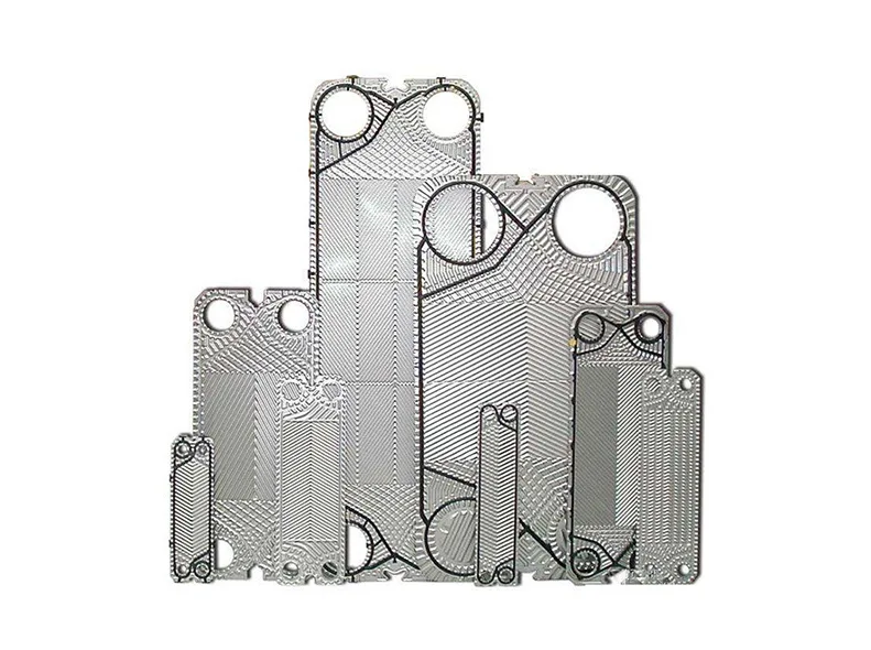
Plate Heat Exchanger Sizing: Step-by-Step Calculation (With a Worked Example)
Aiprel
professor
Aiprel · Technical Guides · November 9, 2026
Ever chosen a plate heat exchanger on rough guesses, only to find it runs hot, never quite reaches the target temperature, or bleeds pressure so badly your pump screams? You are not alone. Oversized units burn capital and floor space; undersized ones drag down production and trigger repeated gasket failures.
The good news: you do not need simulation software to run a solid preliminary sizing. And sizing a plate heat exchanger is not the same exercise as choosing one. In our selection guide — How to Choose the Right Plate Heat Exchanger for Your Process — we covered the qualitative side: construction type, plate and gasket materials, fouling strategy and lifecycle cost. This article goes one level deeper and answers the question engineers ask next: “What size does this unit actually need to be?”
By the end, you will be able to take four or five process numbers and estimate the heat transfer area, the approximate plate count, and whether the pressure drop is plausible — before you send anything to a supplier.
Contents
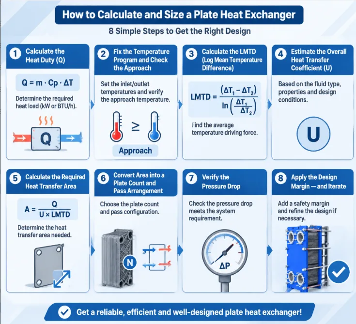
What You Need Before You Start the Calculation Step 1: Calculate the Heat Duty (Q) Step 2: Fix the Temperature Program and Check the Approach Step 3: Calculate the LMTD (Log Mean Temperature Difference) Step 4: Estimate the Overall Heat Transfer Coefficient (U) Step 5: Calculate the Required Heat Transfer Area Step 6: Convert Area into a Plate Count and Pass Arrangement Step 7: Verify the Pressure Drop Step 8: Apply the Design Margin — and Iterate
What You Need Before You Start the Calculation
You only need five inputs for a first-pass plate heat exchanger sizing calculation:
Input
Symbol
Example (used throughout this article)
Hot-side flow, inlet/outlet temperature
m₁, T₁(in), T₁(out)
30 m³/h water, 80 °C → 60 °C
Cold-side flow, inlet/outlet temperature
m₂, T₂(in), T₂(out)
40 m³/h water, 45 °C → 60 °C
Fluid properties (cp, ρ, μ, k)
—
Water on both sides
Allowable pressure drop
ΔP
≤ 50 kPa per side
Construction constraint
—
Single-pass, counterflow, gasketed unit
If you cannot fill in this table yet, start with the selection guide above — it contains the full inquiry checklist to send with your request for quotation. The rest of this article assumes the table is complete.
Step 1: Calculate the Heat Duty (Q)
Heat duty is the amount of heat transferred per unit time. It is calculated from either side of the exchanger — and both sides must agree, which is your first built-in error check.
Required temperature rise: ΔT = Q / (m₂ × cp) = 697 / (11.11 × 4.18) ≈ 15 K
Cold outlet: 45 + 15 = 60 °C ✓ (matches the specification)
⚠️ If the two sides disagree by more than a few percent, one of your flow rates or temperatures is wrong — usually heat loss to ambient, an estimated flow, or a duty taken from an old datasheet. Fix it here, or every downstream number inherits the error.
Step 2: Fix the Temperature Program and Check the Approach
Arrange the four terminal temperatures in counterflow order and compute the temperature difference at each end:
ΔT₁ (hot end) = T₁,in − T₂,out = 80 − 60 = 20 K
ΔT₂ (cold end) = T₁,out − T₂,in = 60 − 45 = 15 K
Two quick sanity checks before any formula work:
The temperature cross (T₂,out > T₁,out) is fine in a plate heat exchanger. Here the cold fluid leaves at 60 °C, the same as the hot outlet. Shell-and-tube designs often cannot approach this; plate units can, because of their high U value and true counterflow. This is one of the main reasons engineers choose PHEs for close-temperature-program duties.
Watch the minimum approach (ΔTmin). Below roughly 1–2 K, every additional degree of approach costs a disproportionate amount of area. If your specified approach is under 2 K, expect a large unit and make sure it is economically justified.
Step 3: Calculate the LMTD (Log Mean Temperature Difference)
Because the temperature difference changes along the plate pack, sizing uses the log mean temperature difference:
[IMAGE-02] Alt text: Counterflow versus parallel-flow LMTD schematic for a plate heat exchanger thermal calculation. Title: LMTD Counter-Flow vs Parallel-Flow. Caption: Counterflow delivers a higher mean temperature difference, which is why most PHE installations run counterflow.
Correction factor F: for a single-pass, true counterflow arrangement, F ≈ 1.0 and is normally taken as 1. For multi-pass arrangements (e.g. 2/2 pass), the flow is no longer purely counterflow and F drops — typically to 0.75–0.95 depending on the pass arrangement and terminal temperatures. If your F lands below about 0.75, the duty is being bought with excessive area; changing to single pass, or re-examining the temperature program, is usually cheaper.
Step 4: Estimate the Overall Heat Transfer Coefficient (U)
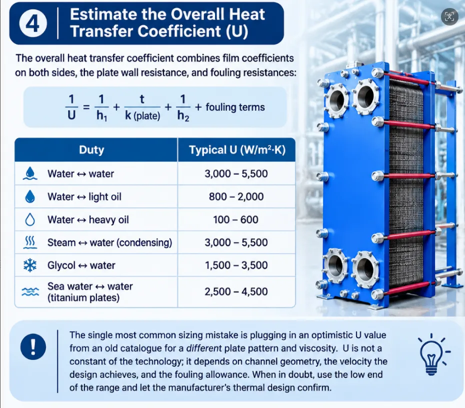
The overall heat transfer coefficient combines the film coefficients on both sides, the plate wall resistance, and fouling resistances:
1/U = 1/h₁ + t/k(plate) + 1/h₂ + fouling terms
You will rarely calculate h₁ and h₂ from Nusselt correlations by hand — plate manufacturers use proprietary correlations specific to each plate pattern. For screening purposes, use typical ranges for water-to-water duties in a gasketed PHE:
Duty
Typical U (W/m²·K)
Water ↔ water
3,000 – 5,500
Water ↔ light oil
800 – 2,000
Water ↔ heavy oil
100 – 600
Steam ↔ water (condensing)
3,000 – 5,500
Glycol ↔ water
1,500 – 3,500
Sea water ↔ water (titanium plates)
2,500 – 4,500
⚠️ The single most common sizing mistake is plugging in an optimistic U value from an old catalogue for a different plate pattern and viscosity. U is not a constant of the technology; it depends on the channel geometry, the velocity the design achieves, and the fouling allowance. When in doubt, use the low end of the range and let the manufacturer’s thermal design confirm.
Worked example: water-to-water, clean industrial duty, moderate fouling allowance → take U = 4,000 W/m²·K.
Step 5: Calculate the Required Heat Transfer Area
The classic sizing equation, solved for area:
A = Q / (U × LMTD × F)
Worked example:
A = 697,000 W / (4,000 × 17.4 × 1.0) = 697,000 / 69,600 ≈ 10.0 m²
This is the effective heat transfer area — the wetted area of plate surface actually doing the work, not the formed area of the plates, and not the footprint of the frame.
Step 6: Convert Area into a Plate Count and Pass Arrangement
Plate manufacturers publish the effective area per plate (Ap). A typical mid-size industrial plate has an effective area around 0.2–0.6 m²; take Ap = 0.30 m² for this example.
N = A / Ap + 1 N = 10.0 / 0.30 + 1 ≈ 34.4 → 35 plates (rounded up)
Notes on the plate count:
The +1 accounts for the final (end) plate, which transfers no heat.
35 plates create 34 channels, i.e. 17 channels per side — a symmetric arrangement, which keeps velocities equal on both sides.
Pass arrangement: with 17 channels per side in a single counterflow pass, both fluids make one traverse of the pack. If the pressure drop on one side turns out too high, the designer can re-arrange into 2 passes on that side — trading a lower F factor (Step 3) for higher channel velocity and better U.
As a screening check, the channel velocity in a gasketed PHE typically lands between 0.3 and 0.8 m/s for water duties. Roughly:
v ≈ m₂ / (n_channels × channel flow area) v ≈ 11.11 kg/s / (17 × ~1.3 kg/s per channel at 0.5 m/s) → within the normal band ✓
If your rough velocity comes out far below 0.3 m/s, the unit will foul and underperform; far above ~1 m/s, pressure drop will be the problem. In either case a different plate size (fewer larger plates, or more smaller plates) is the fix — which is exactly the kind of trade-off the manufacturer’s selection software evaluates.
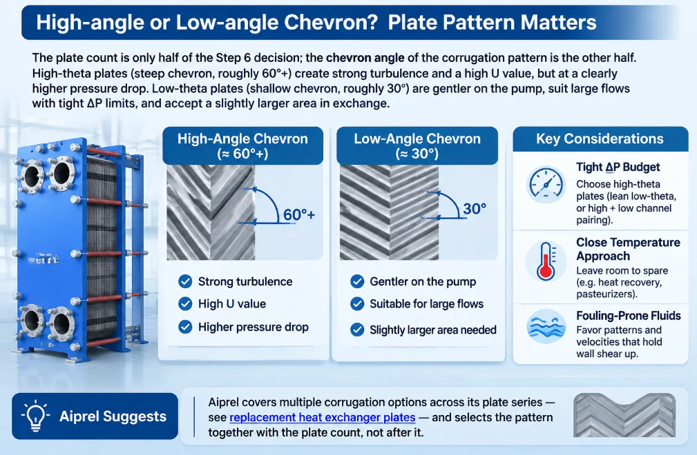
High-angle or low-angle chevron? Plate pattern matters
The plate count is only half of the Step 6 decision; the chevron angle of the corrugation pattern is the other half. High-theta plates (steep chevron, roughly 60°+) create strong turbulence and a high U value, but at a clearly higher pressure drop. Low-theta plates (shallow chevron, roughly 30°) are gentler on the pump, suit large flows with tight ΔP limits, and accept a slightly larger area in exchange.
Tight ΔP budget, high flow (e.g. cooling-water circuits with long piping) → lean low-theta, or a mixed “high + low” channel pairing.
Close temperature approach, ΔP room to spare (e.g. heat recovery, pasteurizers) → lean high-theta to maximize U and shrink the area.
Fouling-prone fluids → favor patterns and velocities that hold wall shear up; a “high U on paper” design that fouls in three months is not a good design.
Aiprel covers multiple corrugation options across its plate series — see replacement heat exchanger plates — and selects the pattern together with the plate count, not after it.
Step 7: Verify the Pressure Drop
Pressure drop has two components in a plate heat exchanger:
ΔP_total = ΔP_channel + ΔP_port
ΔP_channel — friction through the corrugated plate channels; roughly proportional to velocity1.8 and strongly dependent on plate pattern (high-theta vs low-theta chevron angles).
ΔP_port — losses through the inlet/outlet ports and manifolds; significant at high flow with small ports.
There is no honest way to hand-calculate ΔP precisely, because channel friction factors are proprietary. What you can do is check plausibility:
Situation
What it signals
ΔP at limit, area fine
Reduce passes, or choose a plate with a wider channel / lower-theta pattern
ΔP fine, area over
Increase velocity (fewer channels) — U rises, area shrinks, unit gets smaller and cheaper
Both over
Go one plate size up
A useful rule of thumb: in a well-matched water-to-water design, both sides should use their allowable ΔP reasonably fully. A design where the hot side sits at 10 kPa while the cold side is capped at 50 kPa is sending a signal that the channel arrangement is unbalanced.
⚠️ Do not specify an unnecessarily tight pressure-drop limit “to be safe”. Every 10 kPa you give away is heat transfer coefficient you don’t get back — the designer is forced to slow the fluid down, and U falls. Specify the ΔP you can actually afford from your pump curve.
Step 8: Apply the Design Margin — and Iterate
Real thermal design is iterative: change the plate count → velocities change → U changes → area requirement changes. The manufacturer’s software converges this loop in seconds. For your screening estimate, add margin explicitly:
Fouling / ageing margin: 10–15% additional area is typical for water duties (over-sizing beyond ~20% is counterproductive: lower velocity → lower U → more fouling → the very problem the margin was meant to prevent).
Worked example: 10.0 m² × 1.15 ≈ 11.5 m² → about 39–40 plates in the final screening count.
The output of your hand calculation is now a realistic expectation: a single-pass gasketed unit of roughly 35–40 plates of 0.30 m² each, ~700 kW duty, both ΔPs within 50 kPa. That is enough to sanity-check quotations and to know whether a supplier’s proposal is in the right universe.
~35 plates (39–40 with margin), single pass, counterflow
7. Pressure drop
To be confirmed by thermal design; both sides expected < 50 kPa
Five Sizing Mistakes That Show Up Most Often
Using Q from one side only. If hot and cold sides disagree, the input data is wrong — fix it before sizing.
Treating U as a universal constant. U is an output of the channel design, not an input you may freely choose from a table.
Ignoring the F correction factor on multi-pass units, which overstates the effective temperature difference.
Over-sizing “for safety”. Excess area lowers velocity, lowers U, and accelerates fouling — the opposite of the intended margin. Cap over-design near 15–20%.
Specifying an arbitrarily tight pressure drop, which silently caps velocity and therefore U.
What Your Hand Calculation Can and Cannot Do
A first-pass calculation tells you the scale of the unit and whether a quotation is plausible. Final sizing must be done with validated plate correlations and measured friction factors, because:
Nusselt and friction correlations are specific to each plate pattern;
two-phase duties (condensers, evaporators) need dedicated models;
fouling behaviour depends on the fluid, temperature and velocities in ways a fixed margin cannot capture.
That is exactly how we size at Aiprel: your five process inputs go into thermal design software, come back as a plate-by-plate design with guaranteed thermal performance, and the unit is backed by our own replacement plates and gaskets for its whole service life.
Send Us Your Numbers
You now know what information a manufacturer needs and what the calculation will do with it. Send us the completed data table from the top of this article — five numbers — and Aiprel’s engineers will return a sized proposal with guaranteed thermal performance, typically within one working day.Get a Sizing Proposal from Aiprel →
Frequently Asked Questions
1.How do you calculate the heat duty of a plate heat exchanger?
Multiply the mass flow of one side by its specific heat and its temperature change: Q = m × cp × ΔT. Calculate it for both sides — they must match. In the example above, 8.33 kg/s of water cooled by 20 K gives ≈ 697 kW.
2.What is a good LMTD for a plate heat exchanger?
There is no “good” universal LMTD — it is set by your process temperatures, not by the exchanger. Typical water-to-water HVAC duties run at 3–10 K LMTD; industrial process duties are often 10–30 K. What matters is that you size the area against the actual LMTD, using a correction factor F below 1.0 for anything other than single-pass counterflow.
3.What is the U value of a plate heat exchanger?
For water-to-water duties, expect 3,000–5,500 W/m²·K in a gasketed plate heat exchanger — roughly 3–5 times higher than a shell-and-tube unit for the same duty. Oil, glycol and viscous duties fall to a few hundred or thousand. U depends strongly on channel velocity and fouling, so treat published values as ranges, not constants.
4.How many plates does my plate heat exchanger need?
Divide the required area by the effective area of one plate, and add one end plate: N = A/Ap + 1. The real question behind the number is which plate size the design uses — the same 10 m² can be 50 small plates or 17 large ones, and the right choice depends on pressure drop, fouling and connection sizes.
5.Can I size a plate heat exchanger from flow rate alone?
No. Flow rate without temperatures gives no duty (Step 1 is impossible), and duty without terminal temperatures gives no LMTD (Step 3 is impossible). Minimum data: both flow rates or one flow plus the duty, and all four terminal temperatures — the same information set listed in our PHE selection guide.
6.Is there a plate heat exchanger sizing calculator I can use?
Generic online calculators do exist, but almost all of them assume a fixed U value and a fixed plate geometry — exactly the two things that vary most between designs. They are fine for a ballpark figure on standard water duties. For anything with oil, glycol, two-phase flow or a tight ΔP budget, send your data to Aiprel and we will run the calculation on validated plate correlations free of charge, typically within one working day.
7.Why does my plate heat exchanger underperform after a few years?
Almost always fouling or a degraded gasket. A fouled channel loses velocity and U value simultaneously, so performance drops faster than the nominal fouling resistance suggests. Plan the margin per Step 8, and budget for periodic cleaning and replacement plates and gaskets rather than indefinite over-sizing.
Get In Touch With Us
Need pricing? Need samples? Need support? Talk with our team in 24h.