How to Measure Heat Exchanger Plate Dimensions: A Step-by-Step Chart and Tolerances
Aiprel
professor
November 13, 2026
Aiprel Engineering Team
To measure heat exchanger plate dimensions, record these values: overall length and width, horizontal and vertical port centre distances, port hole diameter, plate thickness, chevron angle, channel gap, gasket groove width and depth, hanger and guide-notch position, the port pattern, and the plate count. Measure a clean, flat plate removed from the middle of the pack — never the frame. Port centres need ±0.5 mm, outline ±1 mm and plate thickness ±0.05 mm, which requires a micrometer on the flat edge rather than a caliper across the corrugation.
The rest of this guide explains how to take each reading and how to turn the readings into a drawing a supplier can be held to.
Two engineers once sent us the same plate as 1,186 mm and 1,124 mm. One included the hanging lug; the other measured along the gasket line. The 62 mm difference was a definition, not an error — enough to quote the wrong plate for a 94-plate pack.
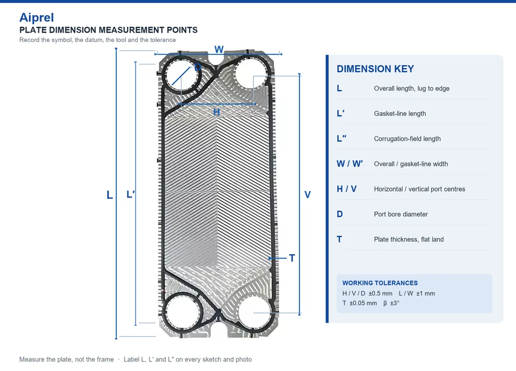
Figure 1. Plate dimension measurement points — L, L′, L″, W, H, V, D and T on a gasketed plate.
The quick answer
Measure the plate, not the frame. Liners and connections add 3–10 mm per side to port spacing.
Define length three ways. Overall length, gasket-line length and corrugation-field length can differ by 30–70 mm on a large plate.
Match the tool to the tolerance. Port centres ±0.5 mm; thickness ±0.05 mm, so use a micrometer on the flat land.
Take the smaller port bore reading, from two axes 90° apart, because the gasket must seal against the minimum effective diameter.
Send a dimensioned sketch plus four photographs, not a list of numbers or a bare frame photo.
One distinction runs through the whole process. Fit-critical dimensions — port centres, bore, outline, lug and notch — decide whether the plate drops into the frame and seals. Performance-critical dimensions — thickness, chevron angle, channel gap, plate count — decide whether the installed pack still meets duty and pressure drop. Fit-critical errors show up on installation day. Performance-critical errors bolt up, pass a hydrostatic test and surface months later as a unit that quietly underperforms.
Table 1. Plate dimensions chart
Use this as the record sheet. “Typical” values are common field examples, not a substitute for the manufacturer’s drawing.
Symbol
Dimension
Where to measure
Typical / example
Working tolerance
Tool
L
Overall length
Lug end to opposite edge, plate flat
1,186 mm in the example above
±1 mm
Steel rule
L′
Gasket-line length
Outside of gasket to outside of gasket
1,124 mm; 30–70 mm shorter than L
±1 mm
Steel rule
L″
Corrugation-field length
Pressed area only, excluding distribution zones
Shorter again
±1 mm
Steel rule
W / W′
Overall and gasket-line width
Across shaped edges; across gasket line
Measure both
±1 mm
Steel rule
H
Horizontal port centre distance
Centre-to-centre, upper and lower pairs
336 mm example
±0.5 mm
Vernier caliper
V
Vertical port centre distance
Centre-to-centre, left and right pairs
Measure both sides
±0.5 mm
Vernier caliper
D
Port hole diameter
True circular opening in the plate, two axes
DN25–DN400 nominal
±0.5 mm
Inside caliper
T
Plate thickness
Flat land outside the gasket groove
0.4 / 0.5 / 0.6 / 0.7 / 0.8 mm
±0.05 mm
Micrometer
β
Chevron angle
Ridge offset over 100 mm of rise
~30° soft, ~45° hard
±3°
Straightedge + rule
b
Channel gap
Derived from tightened pack height
2.0–2.6 mm soft; 1.2–1.8 mm hard; 6–10 mm wide-gap packs
±0.2 mm
Depth rod or calculation
g
Groove width / depth
In the groove, away from port rings
Profile-specific
±0.2 mm
Depth micrometer
—
Lug / notch, port pattern, plate count
Edge to lug centre; notch side; open vs blanked ports; edges at pack top
Four open, or two open + two blanked
±2 mm / exact
Steel rule, count
Why the symbols matter. L = 1186 and L′ = 1124 tells a supplier exactly which span each number describes; “about 1,150 mm long” forces a guess that usually costs a shutdown. Keep the same letters on the sketch, in the photo captions and in the enquiry.
Where the numbers come from. Port spacing and bore are fixed by the pressing tool, so they are the most reliable identification data on the plate. Thickness, angle and gap are chosen for the duty — which is why two plates with identical outlines behave differently. Our step-by-step sizing walkthrough shows how those choices propagate into heat transfer and pressure drop.
Step-by-step: how to measure a plate in the field
Step 1 — Prepare the plate and the datum
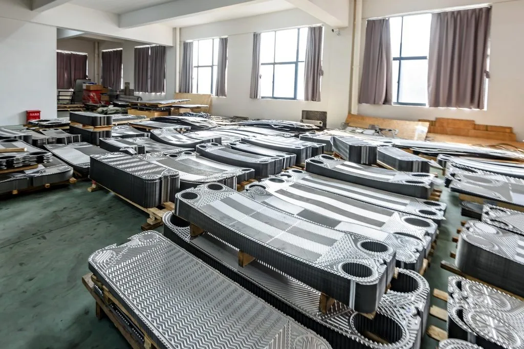
Take a plate from the middle of the pack: end plates corrode first, distort first and are often a different specification. Clean scale and adhesive from the groove, port rings and flat land without wire-brushing the corner stamp — a pencil rubbing or a parallel torch reads a 0.2 mm-deep mark without erasing it. Lay it flat on a rigid level surface and remove the gasket. If the unit has run more than five years, order replacement heat exchanger gaskets before opening it; a gasket that comes off rarely goes back on.
Give the plate an ID, call the lug end “top”, name the guide-bar side, label faces A and B, and log ambient temperature. Stainless expands roughly 16 × 10⁻⁶ per kelvin, so a hot 1,000 mm plate measured against room-temperature tooling differs by about 0.5 mm over a 30 K gap — half the tolerance budget on a port centre distance. Let it reach room temperature first.
Figure 2. Work from a clean, flat plate taken from the middle of the pack; end plates corrode and distort first.
Step 2 — Measure port centre distances H and V
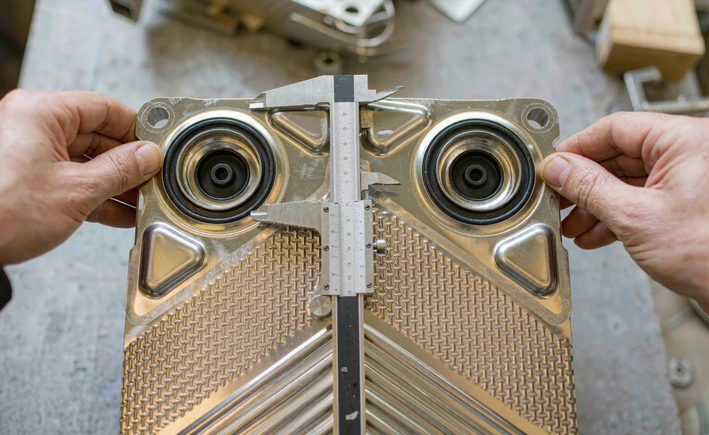
Measure on the plate, never between frame connections. Where the centres are hidden, take the outer span across the two holes and the inner span between them, then average: centre-to-centre = (outer + inner) ÷ 2. Two 76 mm holes on 336 mm centres give 412 mm outside and 260 mm inside; the average returns 336 mm. Repeat on both axes and check the two diagonals of the four-port rectangle — disagreement above roughly 1 mm signals distortion or a mispositioned hole, not an invitation to average. ±1 mm shortlists a plate family; ±0.5 mm places an order.
Figure 3. Check port centres H and V with a vernier caliper directly on the plate — never between frame
Step 3 — Measure port bore, outline, lug and notch
Take two bore readings 90° apart and keep the smaller: ports become oval after years of erosion, and the gasket seals against the minimum effective diameter. Run the tape along the plate edge for outline — stretching it across the corrugation adds 3–5 mm of ridge height. Record L, L′, L″, W and W′ separately. Then measure edge to lug centre and note the notch side explicitly: a plate with the notch on the wrong side hangs slightly rotated and weeps at the bottom corner, a fault routinely misdiagnosed as a gasket problem. Finally record the port pattern — four open holes, or two open and two blanked — because it decides single-pass or multi-pass arrangement.
Step 4 — Measure plate thickness with a micrometer
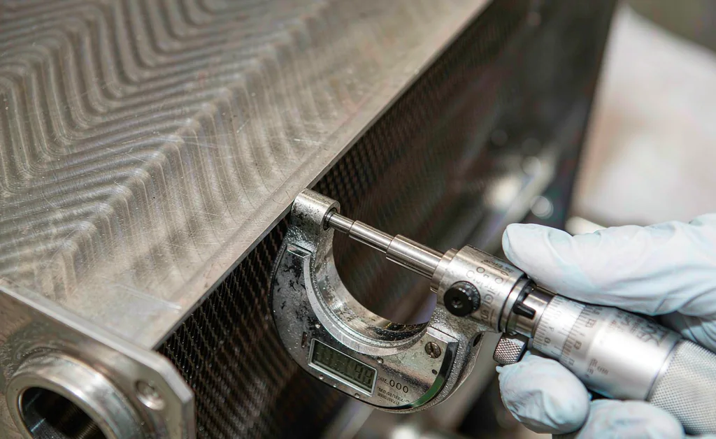
Use the micrometer on the flat land outside the gasket groove, at three points, and keep the lowest: erosion thins a plate locally and the minimum governs. A caliper placed across two corrugation crests reads 1.0–1.3 mm on a plate actually 0.5 mm thick — the single most common wrong quotation we see. Titanium is usually 0.5 or 0.6 mm; a 0.4 mm plate found in seawater duty is often the reason the unit leaks now. Never mix thicknesses in one pack: a 0.6 mm plate fits a pack built for 0.5 mm, then narrows every channel, raises pressure drop and may prevent the pack reaching its marked tightening dimension.
Figure 4. Measure plate thickness T with a micrometer on the flat land outside the gasket groove; keep the lowest of three readings.
Step 5 — Measure chevron angle and channel gap
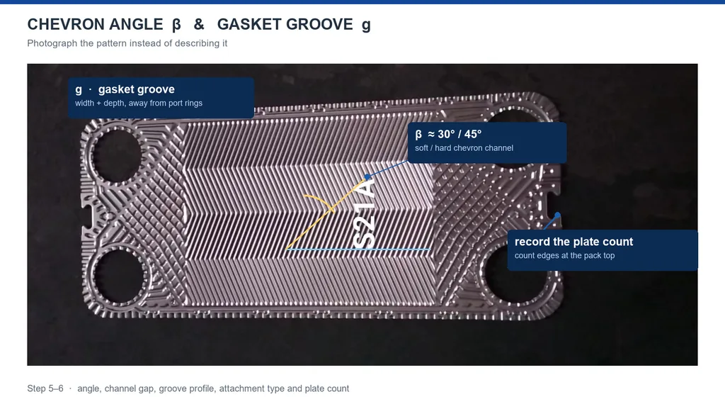
Lay a straightedge along one ridge, mark 100 mm of rise along the long axis and measure the lateral offset: tan θ = offset ÷ 100. About 58 mm indicates 30° (“soft”), about 100 mm indicates 45° (“hard”). Mixed packs alternate the two, so photograph the pattern instead of describing it and confirm the arrangement against the replacement parts enquiry guide. For a closed pack, gap = pack height ÷ (plates − 1) − thickness: a 3.0 mm pitch with 0.5 mm plates gives a 2.5 mm channel. With the pack open, a depth rod and straightedge give a direct reading; disagreement between the two methods tells you the plates are not sitting flat.
Step 6 — Record groove, attachments and plate count
Groove width and depth decide whether existing gasket stock can be reused, and whether clip-on or glued gaskets will seat. Note the attachment type and the gasket compound required by the fluid and cleaning regime. Count plate edges at the top of the pack exactly — the count drives both the order quantity and the channel-gap calculation. Photograph the whole frame, the plate corner, the corrugation close-up and the gasket groove, with the instrument still in position on each dimension shot.
Figure 5. Chevron angle β, gasket groove g and plate count — photograph the pattern instead of describing it.
Why two careful measurements disagree
Error source
Typical size
How it shows up
Control
Definition error
30–70 mm on length
Two consistent readings, irreconcilable
Label L, L′, L″ on the sketch
Instrument error
0.1–1.3 mm
Small repeatable offset; wrong tool
10:1 resolution rule, zero check
Part-condition error
3–8 mm on outline
Readings drift along the edge
Clean, mid-pack plate, flag distortion
The 10:1 rule is the fastest way to choose a tool: resolve roughly ten times finer than the tolerance checked. A ±0.05 mm thickness needs a micrometer at about 0.005 mm; a ±1 mm outline needs a steel rule. Confirm zero on a standard, use the ratchet, inspect jaws for wear, and log the instrument ID and calibration date.
Never average a deformation away. Over-tightening and water hammer can dish a plate 3–8 mm long. If every plate is dished the unit has probably run over-pressure; say so and ask whether the plates or the whole exchanger should be replaced.
Field method vs laboratory method
A caliper, a micrometer and a straightedge resolve most replacement enquiries in half a day on site. Escalate to instrumented inspection in three cases: an undocumented pattern with no markings (optical or 3D scanning captures the corrugation field and groove profile); suspected wall thinning or pressing defects (ultrasonic thickness mapping and a coordinate measuring machine find what three flat-land readings cannot); and a dispute over a delivered batch (traceable dimensional reports give both parties a common acceptance basis).
The distinction is commercial: field measurement identifies what fits, laboratory measurement establishes whether a part conforms to a drawing. At Aiprel, plate pressing on 15 hydraulic presses from 3,000 to 40,000 tons, laser cutting, CNC machining, non-destructive testing and pressure leak testing run inside one ASME-certified workflow, so the team reading a field sketch also produces the controlled drawing and inspection record behind it. See our manufacturing and quality capabilities and the product catalogue for the plate families we hold tooling for.
On standards.ISO 15547-1:2005 sets out requirements for mechanical design, materials, fabrication, inspection and testing of plate-and-frame heat exchangers for petroleum, petrochemical and natural gas industry duties, including gasketed, semi-welded and welded constructions. For general industrial, HVAC, food or marine duties, acceptance is normally governed by the manufacturer’s plate drawing and the purchase order’s technical agreement instead. Agree which drawing revision governs acceptance before releasing an order — a standard citation never replaces a dimensioned drawing.
From readings to an inspectable drawing
Produce one dimensioned sketch. Mark the datum, H and V axes, all three length definitions, D, the port pattern, the lug and the notch, plus units, plate ID, revision and date. A sketch forces a reviewer to confront each definition; bare numbers do not.
Give every value a provenance. Record plate ID and position, date, ambient temperature, instrument ID and calibration date, operator, value, definition used, photo reference and notes on deformation. Mark estimates “to be confirmed” — an estimate presented as exact does more damage than an openly missing value.
Make the supplier respond in the same format. Ask for a marked-up drawing with their dimensions and tolerances, compare line by line, then release production. Most disputes over replacement heat exchanger plates trace back to a value both parties had but only one had defined. Put the agreed revision on the purchase order.
Agree incoming inspection before the parts ship. Verify the first article fully, then apply an agreed sampling plan across the batch for H, V, D, L, T and lug position. Check against the approved drawing or the spare parts library reference — not the old plate in the stores cupboard.
Where measurement stops being enough
Brazed and welded units. There is no serviceable pack and no plate-level geometry. Identification stops at outline, connection size and type, and the decision is a whole unit rather than a part — check which of our gasketed, semi-welded or fully welded constructions fits the duty.
Obsolete series. The model may be identifiable while the tooling no longer exists. The question becomes “what fits this frame now?” — which starts with H and V, since the frame constrains you to families sharing its port spacing. Browse the full plate heat exchanger range when a like-for-like plate is unavailable.
Material and condition. Dimensions cannot tell you whether a plate is 316L, titanium or SMO 254, nor whether a thinned wall still meets design pressure. Ask for material certification and, in aggressive service, positive material identification. A trial fit confirms geometry, never material or long-term reliability.
What to send
Send the record sheet, dimensioned sketch and four photographs, plus the duty (both media, temperatures, flow rates), quantity, port pattern and the original tightening dimension if anyone logged it. The contact page is where the sheet and photos can be uploaded. A complete package usually returns a plate family, a gasket compound, a lead time and a clear answer on the frame’s condition in one exchange; “about 900 mm long” takes four. More guides are in the Aiprel news archive.
Frequently asked questions
How do you measure heat exchanger plate dimensions?
Measure a clean, flat mid-pack plate on a rigid surface. Record overall length and width, horizontal and vertical port centre distances, port hole diameter, plate thickness, chevron angle, channel gap, gasket groove profile, lug and notch positions, port pattern and plate count. Label each value with its reference surfaces and photograph the instrument in position.
What tolerance is needed when measuring plate dimensions?
Half a millimetre on port centre distances, one millimetre on outline, 0.05 mm on plate thickness, about 3° on chevron angle and 2 mm on lug position. Better than that is wasted effort; worse produces a wrong quotation. Mark any dimension you cannot hold as “to be confirmed”.
Can I measure plate dimensions without opening the pack?
Partly. Outline, port positions and the corner stamp can be taken from an end plate; thickness, chevron pattern, groove profile and an exact plate count need a plate out of the pack. Budget half a day on a mid-size unit, and order gaskets before opening a pack that has run for years.
Why does my plate length differ from the supplier’s drawing?
Usually you measured a different span — overall instead of gasket-line, or across the corrugation instead of along the edge. The three length definitions can differ by 30–70 mm. Compare definitions before numbers and ask the supplier to mark the span on a drawing.
Do I need a micrometer, or is a caliper enough?
A micrometer is required for plate thickness: it is the only reading where the tolerance is tighter than a caliper’s useful resolution and a wrong value changes the compressed pack geometry. For outline and port spacing, a sound steel rule or vernier caliper and a clear datum are the right tools.
The reading, in one line
A plate dimension is not a number until it carries a symbol, a datum, a tool and a tolerance: measure the plate rather than the frame, label L from L′ and L″, and send the chart rather than the guess — because the cost of a disputed 62 mm is never paid by the tape.
Get In Touch With Us
Need pricing? Need samples? Need support? Talk with our team in 24h.